555 Timer Ic Schematic Diagram : 555 Timer Tutorial - The Monostable Multivibrator : This circuit is also called a delay.
byAdmin•
0
555 Timer Ic Schematic Diagram : 555 Timer Tutorial - The Monostable Multivibrator : This circuit is also called a delay.. 555 ic timer block diagram 555 ic timer block diagram. 555 timer ic (16) 8051. The first comparator has threshold input to pin 6 and control inputs for pin 5. We can use the 555 as a timer for up to 10 minutes. It was commercialized in 1972 by signetics.
Internal diagram of 555 timer ic. 555 timer ic (16) 8051. The 555 timer ic is an integrated circuit (chip) used in a variety of timer, delay, pulse generation, and oscillator applications. In monostable mode, the duration for. Ic 7555 is the cmos version of the 555 ic with same pin configuration and function.
Monstable Multivibrator using 555 Timer from electrosome.com Dec 07, 2018 · the ic 556 and ic 558 are 14 pins dual timer and 16 pin quad timer versions of the ic 555 respectively. Simple ne555 ic tester circuit diagram. In monostable mode, the duration for. Ic 7555 is the cmos version of the 555 ic with same pin configuration and function. All we need to change the value of resistor r1 and/or capacitor c1. The 555 timer ic is an integrated circuit (chip) used in a variety of timer, delay, pulse generation, and oscillator applications. A tutorial on how to make an adjustable delay timer circuit using 555 ic that can automatically turn on/off any output after a fixed duration. Apr 15, 2020 · people know it as the 555 timer ic.
Derivatives provide two or four timing circuits in one package.
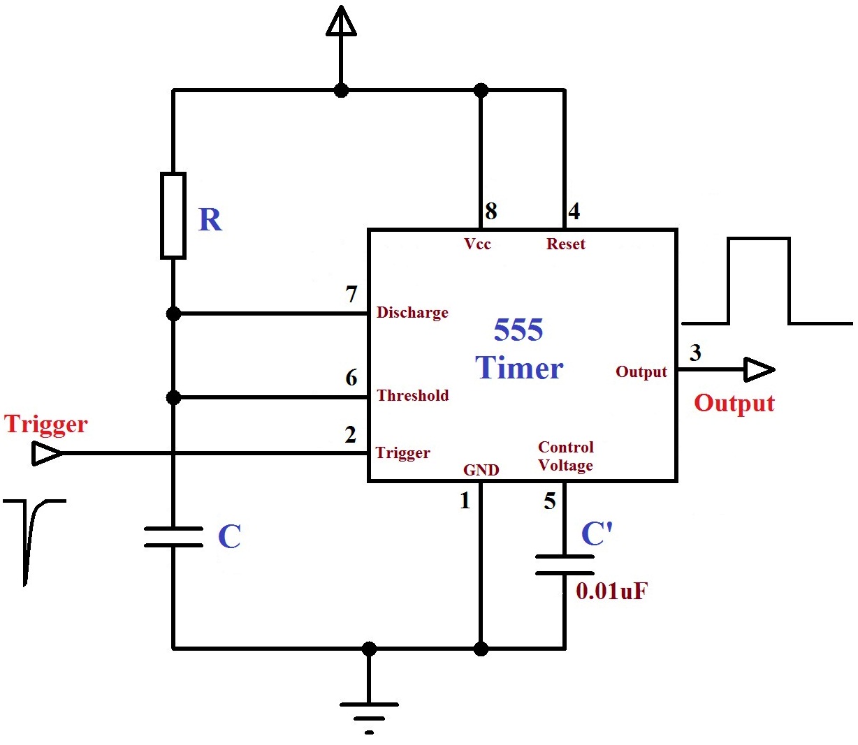
The block diagram of a 555 timer is shown in the above figure. Resistive network consists of three equal resistors and acts as a voltage divider. We can use the 555 as a timer for up to 10 minutes. The first comparator has threshold input to pin 6 and control inputs for pin 5. Simple ne555 ic tester circuit diagram. All we need to change the value of resistor r1 and/or capacitor c1. Jul 14, 2015 · we can use this property of 555 timer to create various timer circuits like 1 minute timer circuit, 5 minute timer circuit, 10 minute timer circuit, 15 minute timer circuit, etc. Apr 15, 2020 · people know it as the 555 timer ic. Ic 7555 is the cmos version of the 555 ic with same pin configuration and function. 555 internal circuit consists of three series 5k resistors connected between the vcc and gnd. This circuit is also called a delay. The control input is used in some of the applications, but most of the applications the control input is not used hence the control voltage is equal to +2/3 vcc. It was commercialized in 1972 by signetics.
The block diagram of a 555 timer is shown in the above figure. Internal diagram of 555 timer ic. We need to set 555 timer in monostable mode to build timer. Derivatives provide two or four timing circuits in one package. The first comparator has threshold input to pin 6 and control inputs for pin 5.
buyhere22 - 556 Timer IC from buyhere22.com We can use the 555 as a timer for up to 10 minutes. Ouput at pin 3 is low. Dec 07, 2018 · the ic 556 and ic 558 are 14 pins dual timer and 16 pin quad timer versions of the ic 555 respectively. It was commercialized in 1972 by signetics. The control input is used in some of the applications, but most of the applications the control input is not used hence the control voltage is equal to +2/3 vcc. Sep 29, 2015 · operation of monostable multivibrator mode of 555 timer ic: A tutorial on how to make an adjustable delay timer circuit using 555 ic that can automatically turn on/off any output after a fixed duration. Operation is simple, initially 555 is in stable state i.e.
It was commercialized in 1972 by signetics.
Resistive network consists of three equal resistors and acts as a voltage divider. We can use the 555 as a timer for up to 10 minutes. A tutorial on how to make an adjustable delay timer circuit using 555 ic that can automatically turn on/off any output after a fixed duration. Learn by doing is the best. 555 timer ic (16) 8051. Simple ne555 ic tester circuit diagram. This circuit is also called a delay. Internal diagram of 555 timer ic. It was commercialized in 1972 by signetics. The control input is used in some of the applications, but most of the applications the control input is not used hence the control voltage is equal to +2/3 vcc. Operation is simple, initially 555 is in stable state i.e. Ic 7555 is the cmos version of the 555 ic with same pin configuration and function. Derivatives provide two or four timing circuits in one package.
555 timer ic (16) 8051. Jul 14, 2015 · we can use this property of 555 timer to create various timer circuits like 1 minute timer circuit, 5 minute timer circuit, 10 minute timer circuit, 15 minute timer circuit, etc. Sep 29, 2015 · operation of monostable multivibrator mode of 555 timer ic: This circuit is also called a delay. Resistive network consists of three equal resistors and acts as a voltage divider.
555 Timer Assembly Instructions | Synthrotek from www.synthrotek.com We need to set 555 timer in monostable mode to build timer. Ouput at pin 3 is low. Simple ne555 ic tester circuit diagram. The 555 timer ic is an integrated circuit (chip) used in a variety of timer, delay, pulse generation, and oscillator applications. All we need to change the value of resistor r1 and/or capacitor c1. Ic 7555 is the cmos version of the 555 ic with same pin configuration and function. Internal diagram of 555 timer ic. Jul 14, 2015 · we can use this property of 555 timer to create various timer circuits like 1 minute timer circuit, 5 minute timer circuit, 10 minute timer circuit, 15 minute timer circuit, etc.
Simple ne555 ic tester circuit diagram.
Simple ne555 ic tester circuit diagram. 555 timer ic (16) 8051. The first comparator has threshold input to pin 6 and control inputs for pin 5. Internal diagram of 555 timer ic. Jul 24, 2019 · the working principle of the 555 timer is by considering the block diagram of the 555 timer ic. Operation is simple, initially 555 is in stable state i.e. 555 ic timer block diagram 555 ic timer block diagram. Sep 29, 2015 · operation of monostable multivibrator mode of 555 timer ic: All we need to change the value of resistor r1 and/or capacitor c1. Derivatives provide two or four timing circuits in one package. We need to set 555 timer in monostable mode to build timer. Resistive network consists of three equal resistors and acts as a voltage divider. The block diagram of a 555 timer is shown in the above figure.
Jul 14, 2015 · we can use this property of 555 timer to create various timer circuits like 1 minute timer circuit, 5 minute timer circuit, 10 minute timer circuit, 15 minute timer circuit, etc 555 timer schematic. 555 internal circuit consists of three series 5k resistors connected between the vcc and gnd.